Summary The loosening of threaded joints has been plaguing engineering and academia. In principle, the reasons for the looseness of the threaded connection are analyzed. Some commonly used anti-loose methods are introduced, and several new anti-loose methods are highlighted. Threaded joint is an important way of joint, widely used in machinery, automobiles, trains, aerospace and other fields. However, when the dynamic load or working temperature of the vibration, load, impact, etc. changes greatly during use, the threaded joint may be loosened, and the friction and preload of the joint will be gradually reduced after repeated times. It even disappears, causing the threaded joint to fail. When the threaded joint fails, it will have serious consequences. The lighter will affect the normal operation of the equipment, and the heavy one will cause the machine to be destroyed. Therefore, the problem of thread anti-looseness has become an actual technical problem and academic problem that need to be solved urgently. 1, the reason for the loose connection of the thread When the static load and the operating temperature do not change much, the tightening of the threaded connection does not occur automatically, and the connection is very reliable. If the threaded joint works in an environment with impact, vibration, variable load or high temperature and large temperature change, the frictional force and pre-tightening force of the joint will gradually decrease or even disappear, and the threaded joint will be loosened after repeated times. And finally expired. Studies have shown that there are three main reasons for the loosening of the threaded connection: (1) Initial deformation of the threaded coupling. In a threaded joint, the initial deformation of the threaded coupling exhibits plastic deformation, which continues to exist in the threaded joint operation and, under certain conditions, expands. It is because of this initial deformation that the initial loosening of the threaded joint occurs. (2) The role of axial load. When the bolt is subjected to an axial load, the bolt is axially elongated, radially elastically contracted, and the nut is radially expanded. Thereby a slight amount of relative radial sliding occurs between the contact faces of the two. At the same time, the relative radial sliding continues to increase under the repeated action of the load, eventually causing the nut to loosen and rotate. (3) The role of lateral loads. When the bolt is subjected to repeated lateral forces, the bolt is elastically twisted (shown in Figure 1). The elastic torsional deformation increases continuously, and the initial displacement of the torsional deformation is formed. The phenomenon of the sliding component also appears in the spiral direction of the spiral pair, and finally the loosening of the threaded connection occurs. The effect of the transverse load is the main cause of the looseness of the threaded joint. Figure 1 Schematic diagram of loosening when threaded joints receive lateral loads 2, commonly used thread connection anti-loose method To prevent loosening and failure of the threaded joint is to prevent relative rotation between the bolt and the nut. Although there are many anti-loose techniques and anti-loose structures for threaded coupling, the working principle can be divided into frictional anti-loose, mechanical anti-loose, and destructive motion-related relationship. 2.1 Friction and anti-loose This type of anti-loose method is to prevent the coupling from loosening by maintaining a certain axial pressure between the tightened thread pairs by means of the pre-tightening method to maintain a certain frictional resistance moment. Commonly used frictional anti-loose methods include a counter nut, a spring washer, a wave spring washer, a conical spring washer, and a self-locking nut. Generally speaking, the friction and anti-loose structure is simple and easy to operate, but its anti-loose reliability is poor, and it is not suitable for use in vibration, shock and dynamic load conditions. 2.2 Mechanical anti-loose This type of anti-loose method utilizes various metal stop elements to prevent relative movement between the nut bolts. Commonly used mechanical anti-loosening methods include a split pin and a hex nut, a stop washer, a tandem wire, and the like. The anti-loose method is suitable for occasions with large vibration, impact, and high speed, especially in the case where the inside of the machine is difficult to inspect, and the anti-loose is reliable, but it is not easy to disassemble. 2.3 Destroying the relationship between sports and anti-loose This is a permanent way to achieve the purpose of loosening by breaking the thread pair. Commonly used methods of anti-corrosion of the destructive motion are riveting, punching, brazing, etc. This method is reliable and can not be reused. 3, the new thread connection anti-loose method 3.1 Self-locking nut The self-locking closing nut is formed by radially closing the end of the nut cylinder to deform the threaded hole of the nut closing portion, and when the bolt is screwed into the nut closing portion, an interference fit is generated and a friction torque is generated on the surface of the thread pair to prevent Loose effect. Commonly used self-locking nut closing methods are two methods: flattening method and point closing. The shape of the flattening method is shown in Figure 2. The point closing is to press and deform several points of the nut closing part, and there are two points, three points and four points to close the mouth. Figure 2 Schematic diagram of self-locking nut closing 3.2 ST2 self-locking locknut The ST2 self-locking locknut is a new type of locknut developed in China. It is achieved by increasing the self-locking friction torque against loosening and damping and loosening. The ST2 self-locking locknut is optimized for the shape of its internal threads, as shown in Figure 3. When the nut and the bolt are matched, a tight state is formed, which causes a slight deformation of the thread pair in the radial direction, which eliminates the radial gap between the nut and the bolt, and at the same time generates a large friction force, thereby achieving the purpose of preventing loosening. Figure 3 Schematic diagram of ST2 self-locking locknut 3.3 nylon ring locking locknut The nut is shown in Figure 4 with a nylon ring embedded at the end of the nut. When the nut is tightened on the bolt, the inner hole of the nylon ring is swollen and elastically deformed, and the nylon ring presses the thread from the radial direction to tighten the bolt, thereby preventing the loosening. A distinctive feature of the nylon ring locking locknut is that there is still friction between the nut and the bolt when the bolt loses axial force. Figure 4 Nylon ring locking locknut 3.4 Iron-based shape memory alloy locknut The iron-based shape memory alloy locknut utilizes the special properties of the material to achieve the purpose of preventing loosening. Iron-based shape memory alloy is a new functional material with shape memory effect. This kind of nut is processed by this characteristic. The internal thread of the nut is processed to be slightly smaller than the external thread of the bolt, and then the internal thread of the nut is deformed to the standard size by the reaming deformation, and the stress generated in the reaming deformation may cause The martensite of the material undergoes a phase change. When the nut is tightened and heated, the resulting stress induces a reverse phase transformation of the martensite. At the same time, the shrinkage of the nut will produce a large radial restoring force. This restoring force is finally converted into a frictional torque between the thread pairs, so that the locking torque between the thread pairs is greatly increased, and the relative rotation between the bolts and nuts is effectively prevented, thereby achieving thread locking. Figure 5 Schematic diagram of concave and convex double nut 3.5 bump double nut anti-loose The concave-convex double nut adopts the principle of concave-convex fitting. One of the two nuts has a concave structure, the other nut has a convex structure, and the concave-convex fitting portion is designed with a certain amount of eccentricity. During operation, an axial and radial pressing force is generated between the mating faces of the nut bolts by the eccentric amount, and a sufficient friction torque is generated to prevent the relative movement between the nut and the bolt, thereby preventing the loosening. 3.6 two-way locknut The two-way locknut, also known as Down's thread, uses two nuts with different threaded threads for locking. There are also two different threads to be machined on the screw. The two threads can be on the same thread segment or not on the same thread segment, as shown in Figure 6. One nut acts as a fastening and the other acts as a locking. In the working direction, the tightening direction of the locking nut is the direction in which the fastening nut is retracted, and the tightening of the locking nut limits the loosening of the fastening nut, thereby The threaded connection does not appear loose. Figure 6 two-way locknut 3.7 Step-type locking bolts (SLB) The spirals of the threads of this type of bolts are stepped and consist of several sections of thread with a pitch, each of which consists of two parts, the step and the inclined part. The former has a helix angle of 0°, the latter has a spiral angle. When the SLB bolt is tightened, the axial force is absorbed by the stepped portion. Therefore, the nut and the bolt do not slide relative to each other in the direction of the spiral, and the anti-loosening purpose is achieved. Conclusion In order to solve the problem of anti-looseness of threaded joints, engineering and academia not only improve and optimize the structure of threaded joints, but also develop a number of effective anti-loosening methods from the materials of fasteners. In the face of specific anti-loose problems, it is necessary to find out the reasons for the looseness of the threaded joints from the principle, and select a reasonable joint structure according to actual reasons, and take reasonable anti-loose measures.
Aluminum die casting Motor Metal Craft
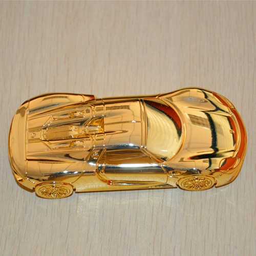
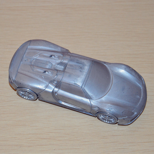
Name: High Pressure Aluminium Die Casting for 80mm Gold Porsche Car Model
Product
Aluminum die casting Car Model
Application
Used Die cast Machine
(Depend on mould)
Die casting machine 120 ton -800 ton
Main Processes Flow
(depends on part shape and requirement)
Drawing / or Samples →Mould making →Die casting →Deburring →Drilling and Tapping →CNC Machining →Polish→Surface treatment →Assembly →Quality inspection → Packing →Shipping
Production Flow
Drawing/ or samples → Mould making →Die casting and other processes →Get samples and send samples to customer for approval → Mass Production ( casual inspection avoid unintentional situation) → QC → Packing →Shipping →Cycle to next order
Surface Treatment (Optional by customer)
Polishing, Sandblasting, Painting, Powder coating, Galvanizing, Chrome plating
Anodizing , Real gold coating, Imitation gold,
Aluminum Craft,Aluminum Motor Metal Craft,Aluminum Metal Car Crafts,Aluminum Die Casting Crafts Dongguan Hongge Hardware Technology Co., Ltd , http://www.honggecasting.com


Apolication: used for all sorts of model for car, craft, plane etc
Specification: custom as per provided product design drawing
Material: Aluminum die casting alloys (97-99% Al, other Silicon, Iron, copper, Magnesium, Manganese, Nickel, Zinc, Tin, Titanium)
Feature: heat resistance, pretty appearance, light weight, water proof, corrosion resistance
Production standard: DIN / JIS / ASTM / MIL
Scale Model


Locking method for threaded joint
Product Description