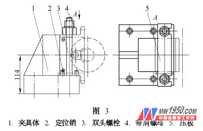
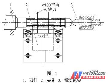
As a first-line engineering and technical personnel, in the process of product processing design, the actual situation of the equipment of the enterprise (company) should be fully considered, and the utilization rate of existing equipment should be maximized to reduce capital investment and obtain maximum economic benefits. 1. Lathe machining theoretical characteristic <br> <br> milling rotary motion into linear motion of the tool and the workpiece, and processing properties and processing characteristics turning milling contrary. Based on this feature, we designed the corresponding milling cutter and fixture to realize the milling function of the lathe. (2) The fixture design is shown in Figure 3. The fixture has a simple structure and convenient loading and unloading. When using, the clamp is mounted on the sliding plate of the lathe, and the specific bottom surface of the clamp is 114mm from the center of the workpiece (that is, the center of the spindle rotation). The linear movement of the workpiece is completed by moving the slide plate manually or automatically during work. Adding a milling cutter bar and corresponding clamping device to the lathe, as shown in Figure 4, completes the milling function of the lathe. For more articles, please refer to "Mechanical Workers" Cold Processing 2007 No. 1 125mm (5 Inch) Flat Cut-off Disc B&H TOOLS CO., LTD. , https://www.bandhtools.com
In the production process, different processing techniques are often encountered to meet the requirements of the drawings, which provides a practical theoretical basis for our machine tool transformation.
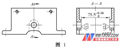
Figure 1 is a part of the processing of our company, originally processed on the milling machine (X5032) 75. 5mm size of the internal cavity of the part. However, due to the fact that the company's actual situation is that the milling machine is in short supply and the C6140 has more lathes, this process has been processed on the lathe by designing the milling cutter bar and the jig, and has received good results. 
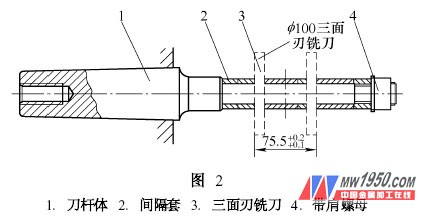
2. Milling shank, fixture structure characteristics and use method (1) As shown in Figure 2, the milling cutter bar consists of shank body 1, spacer sleeve 2, three-sided edge milling cutter 3, with shoulder nut 4. The end of the milling cutter rod is designed with an internal thread with a guard cone, and the front end is designed with a central hole with a guard cone. When using, the Morse taper part is placed in the spindle of the lathe. In order to prevent the milling cutter stem from damaging the lathe spindle due to excessive force, the milling cutter rod can be fixed on the lathe main shaft by the internal thread of the tail. The two-sided three-sided milling cutter is mounted on the milling cutter. The position and spacing are determined by the size of the fixture and the workpiece. Figure 1 shows that the inner cavity size of the part is 75. 5 mm, so the outer spacing of the two blades is adjusted to 75. 5mm (can be adjusted by the spacer sleeve in the middle of the three-sided milling cutter). The front end of the milling cutter rod is tightened by the movable top placed in the tailstock of the lathe to increase the overall rigidity of the milling cutter. The central hole of the front end of the milling cutter is designed with a protective cone to effectively prevent the center hole from colliding. In this way, when the spindle is running, the milling cutter can be driven to complete the rotary motion of the cutter under the support of the tip of the tailstock. 

