Radar Level,Radar Level Meter,Radar Level Gauge,Radar Level Sensor Wuxi Winsun Automation Instrument Co., Ltd , https://www.jswxwinsun.com
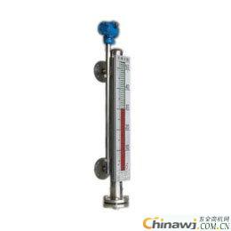
The magnetic flap level gauge consists of a body, a flap box (composed of red and white two-color magnetic small flaps), a float, a flange cover, etc., and is used for liquid Level Measurement of various liquid containers. Magnetic flap level gauge can be used for high temperature, explosion-proof, anti-corrosion, food and beverage, etc., for local display or remote display and control of liquid level. UHZ series magnetic flap level gauge can achieve high sealing, anti-leakage and safe and reliable measurement of liquid level under high temperature, high pressure, high viscosity and strong corrosive conditions. The whole process measurement has no blind zone, the display is eye-catching, the reading is intuitive, and The measuring range is large, equipped with liquid level alarm and control switch, which can realize the upper and lower limit alarm and control of liquid level or boundary. It can be equipped with HN series liquid Level Transmitter to set the liquid level. The boundary signal is converted into a standard signal of two-wire 4~20mADC to realize remote detection, indication, recording and control. HN UHZ series magnetic flap level gauges are widely used in liquid level measurement and control in the production process of electric power, petroleum, chemical, metallurgy, environmental protection, shipbuilding, construction, food and other industries.
1. The magnetically permeable plate is not allowed to be close to the body of the magnetic flap level gauge, and the wire is fixed. Otherwise, it will affect the normal operation of the magnetic flap level gauge;
2. If the user uses the heating circuit by himself, he must use non-magnetic materials, such as copper tubes. The heat tracing temperature is determined according to the medium condition;
3. The installation of the magnetic flap level gauge must be vertical. A ball valve should be installed between the magnetic flap level gauge and the container guide tube for easy inspection and cleaning;
4. The medium should not contain solid impurities or magnetic substances to avoid jamming the float;
5. Before use, the ball below the zero position should be set to red with the correct magnetic steel, and the other balls should be set to white;
6. Open the bottom flange and insert the magnetic float (note: the end of the heavy end with the magnetic end up, can not be flipped.);
7. When commissioning, first open the upper pilot valve, then slowly open the lower valve to allow the medium to smoothly enter the main conduit (the medium should avoid the rapid impact of the float during operation, causing the float to fluctuate and affect the display accuracy). Observe the magnetic red and white ball. Whether the flipping is normal, then close the lower pilot valve, open the drain valve, and let the liquid level in the main conduit drop. According to this method, it is normal, and it can be put into operation (except for special liquids such as corrosive);
8. The main conduit should be cleaned from time to time to remove impurities according to the medium;
9. For liquid level gauges exceeding a certain length (common type > 3 meters, anti-corrosion type > 2 meters), it is necessary to increase the intermediate reinforcement flange or ear climbing as a fixed support to increase the strength and overcome its own weight;
10. The installation position of the magnetic flap level gauge should be avoided or away from the inlet and outlet of the material medium to avoid rapid changes in the local area of ​​the material fluid and affect the accuracy of the liquid level measurement;
11. When equipped with remote transmission instruments, the following must be done:
(1) The remote transmission supporting instrument should be closely attached to the main pipe of the liquid level gauge and fixed with stainless steel hoop (disabling iron);
(2) The sensing surface on the remote transmission supporting instrument should face and close to the main conduit;
(3) The zero position of the remote transmission supporting instrument shall be on the same horizontal line as the zero position indication of the liquid level gauge;
(4) The connection between the remote transmission supporting instrument and the display instrument or the industrial computer is preferably laid by a protective tube alone or with a shielded two-core cable;
(5) After the wiring box of the junction box is laid, the sealing is required to be good, so as to prevent the intrusion of rainwater and moisture, so that the remote supporting instrument can not work normally. The junction box should be covered in time after the repair or debugging is completed. 