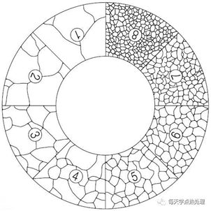
â— Materials are generally classified into structural materials and functional materials according to their performance and use. The structural material is mainly characterized by mechanical properties; the functional materials are mainly characterized by physical and chemical properties. The difference in performance between the two is determined by the microstructure and element properties. â—† failure defect â— Accident investigation conclusions After testing the material properties of the Titanic shipboard spare parts, it was found that there were a large number of MnS inclusions, and the vertical and horizontal ductile-brittle transition temperatures were 320C and 560C, respectively, and the water temperature at that time was -20C. Fishbone diagram for failure analysis â— Failure analysis is post-mortem analysis. The best method should be pre-analysis, such as FMEA (Failure Modes and Effect Analysis), RBI (Risk-based Inspection), etc. Deformation failure <br>Elastic deformation failure----Excessive elastic deformation, although no damage marks are found on the surface, but the elastic properties have not reached the original design requirements. For example, automotive springs, after long-term use, the relaxation performance is reduced, which can not be used for cushioning. Plastic deformation, failure, plastic deformation failure----the deformation amount exceeds the limit and can no longer be used. After long-term operation, the steam turbine blades gradually extend and plastically deform and come into contact with the casing, so that the steam turbine cannot operate normally. Dimple-deformation section SEM Fracture failure---brittle fracture <br>Fracture fracture refers to the fact that almost no significant plastic deformation occurs before fracture. The path of crack propagation is divided into transgranular brittle fracture and intergranular brittle fracture. Quasi-cleavage-brittle section SEM Fracture failure--brittle fracture--- brass brittle fracture <br>The brittle fracture of metal material caused by crack propagation along the grain boundary is called intergranular brittle fracture. Generally, the grain boundary is a strengthening factor, that is, the bonding force of the grain boundary is higher than that of the crystal, and the intergranular fracture is generated only when the grain boundary is weakened. Fatigue mode Tire pattern Dimple belt Secondary crack zone Common causes of fatigue fracture <br>Fatigue fracture caused by insufficient material strength; Macroscopic characteristics of fatigue fracture Fatigue striation Corrosion failure <br> point corrosion crevice corrosion grain boundary corrosion stress corrosion Stress corrosion Corrosion failure----corrosion fatigue Hydrogen embrittlement fracture Wear failure Crack source identification method - macro analysis China's material status Materials urgently needed for key projects <br>25% of domestic production is not available; or 46% is not guaranteed; 71% in total Many key products cannot be independently developed. For example: welding materials for nuclear power; ultra-supercritical turbine rotors, inner cylinder materials; high-performance bearing materials; advanced composite materials. The notch form of the impact specimen has a great influence on the impact toughness. The Charpy V-notch is sharper than the Charpy U-shaped notch, and is more sensitive to the notch sensitivity of the material and its internal defects under dynamic load. Shrinkage hole looseness: The round billet has a large height-to-diameter ratio and a long liquid core, which cannot achieve long-term feeding, and there is a through-hole shrinkage hole in the center. Typical defects of large continuous casting large round billets Grain size Non-metallic inclusions Heating and cooling defects Welding defect Shrinkage hole - low magnification defect Fracture micromorphology analysis Fracture micromorphology analysis Mechanical Properties Testing <br>The Metals Laboratory provides authoritative testing and evaluation of mechanical properties. Mechanical testing methods include: deformation, fracture, adhesion, creep, fatigue, etc. Testing Scope Nondestructive testing
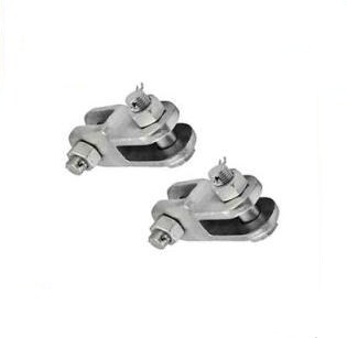
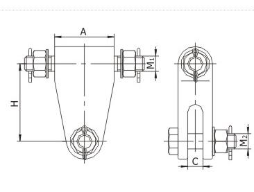
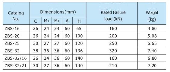
Zbs Clevise is Link Fitting. Link fitting is used for insulators, Suspension Clamp, clamp and protection fittings connected to form a suspension or tension string set of fittings.
ZBS Clevises are used to attach clevis tongue insulators to various associated hardware within an insulator string.
ZBS Clevise is widely used to connect insulator & insulator, or connect insulator and ground wire clamp to tower arms or subjection structures. The cotter pin are stainless steel, the other parts are hot-dip galvanized steel.
If you have any questions, please contact with us directly.
ZBS Clevise Zbs Clevise,Zbs Type Clevise,Link Fitting Zbs Clevise,Zbs Clevis For Overhead Line Accessories Shandong Vantage International Trade Co., Ltd. , https://www.steelplate.be
â— The failure behavior of materials depends mainly on changes in microstructure and macroscopic morphology. Determining the relationship between failure modes, failure mechanisms, failure defects and failure causes of different materials is the core content of the failure analysis discipline.
Invalid meaning:
National Standard GB3187-82 "Basic Terms and Definitions of Reliability"
The definition of the failure: "The product loses the prescribed function, and the repairable product is often called a fault."
â—† Definition of the Material Dictionary*
Failure, also known as the failure of a composite material, means that the composite material loses its specified function after undergoing certain physical and chemical processes (such as load action, material aging, temperature and humidity changes, etc.) in terms of size, shape, and performance. .
â—† Definition of the American Society for Metals Handbook*
According to the definition of ASM Handbook, any component of the service is ineffective when it appears in one of three states:
(1) When it cannot be repaired at all;
(2) It can still be used, but it cannot be satisfactorily achieved when the specified function is achieved;
(3) When it is seriously damaged and cannot be used safely and reliably.
Failure analysis relationship
â— Failure analysis is to clarify the relationship between failure modes, failure defects, failure mechanisms and failure causes. â—† Failure mode (failure mode)
The failure mode refers to the appearance of the component after failure, and the macroscopic characteristics of the observed and measurable failure. For example, brittle fracture,
Fatigue cracking, contact wear, etc.
There are five types:
(1) fracture
(2) Corrosion
(3) wear
(4) Distortion
(5) Attenuation: The microstructure is gradually weakened with time.
Relationship between failure mode and failure mechanism of metallic materials 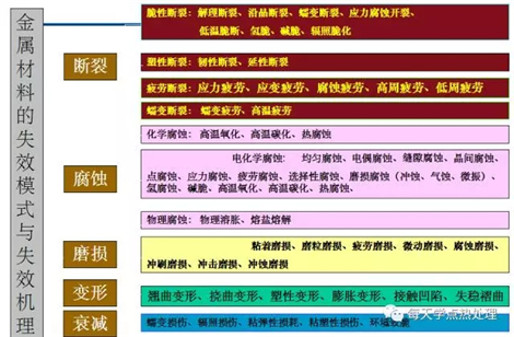
A failure defect is a practical defect that causes damage (damage) to the component. For example, cracks, corrosion pits, wear strips, delamination, etc.
â—† failure mechanism
The failure mechanism is the physical and chemical change process that causes the failure of the component, that is, the microscopic mechanism of failure. For example, galvanic corrosion, crevice corrosion, grain boundary corrosion, pitting, etc. in corrosion mode.
â—† failure cause
The cause of failure is a key factor in the failure mechanism. For example, overload, fatigue load, electrode potential difference, fretting friction, and the like.
â— Titanic's failure mode, mechanism, defects and causes. The Titanic is the world's largest luxury cruise ship in the early 20th century.
It is 260m long, 28m wide, 51m high and 46,328t tonnage. It can carry more than 3,000 passengers and costs a total of 75 million pounds. The hull structure was designed with a double-shell and sixteen isolated watertight compartments and was considered a "never-sinking" wheel.
Its maiden voyage departed from Southampton, England, to New York on April 10, 1912, at a speed of 22 knots, but collided with a floating iceberg in the North Atlantic at 11:40 pm on April 14 due to the hull. The six watertight compartments on the left all broke into the water and sank after 2 hours and 47 minutes.
There were 2,208 people on board, only 705 people were rescued, and 1,503 people were buried on the seabed. This is the largest maritime accident ever occurred in the world. 
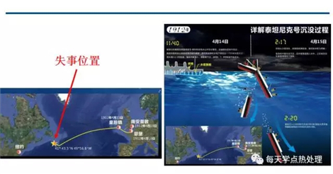

It can be assumed that the failure characteristic of the Titanic collision with the iceberg is brittle fracture (failure mode), because the ship plate and the rivet contain a large amount of MnS inclusions and other harmful elements such as P. The ship plate caused many cracks (failure defects) under the impact of the iceberg. These cracks then experienced rapid fatigue expansion (failure mechanism) under the continuous action of the waves, which eventually led to the hull fracture.
Therefore, the failure of the Titanic is caused by the fatigue brittle fracture that occurs under the interaction of a large number of MnS inclusions and iceberg impact forces in the ship's slab and rivet (failure cause).
Failure analysis strategy
â— Product Quality Management Law
â—† "Five Elements Method"
"People, Machine, Material, Law, Ring" (4M1E Analysis Method)
â—† "Six element method"
"People, Machine, Material, Law, Ring, Measurement" (5M1E Analysis Method)
â— Failure analysis and analysis of components must not only have expertise in materials, processes, structures, mechanics, control, but also engineering knowledge in installation, operation, maintenance, and environment, as well as familiarity with standards, norms, procedures, and psychology. Some management knowledge within.
â— Influencing factors of failure
(1) Material selection is not suitable
(2) Insufficient structural design
(3) General quality of manufacturing
(4) Improper installation
(5) Test method routine
(6) The personnel operation is incorrect
(7) Maintenance process omissions
(8) Working condition medium complex
(9) Changes in external environment
(10) The mechanism of failure is unknown
(11) Simple protection measures
(12) The management system is not strict
â— Completeness of failure analysis From a technical point of view, a complete failure analysis should consider eight factors:
(1) design
(2) material
(3) Fabrication
(4) Installation
(5) Inspection (inspection)
(6) operation
(7) maintenance (maintenance)
(8) Environment (environment) 
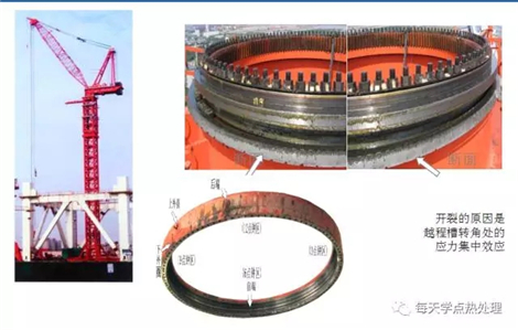
Creep deformation failure----Parts under long-term high temperature and stress, even if less than the yield stress will slowly produce plastic deformation, this phenomenon is called creep, when the creep deformation exceeds the specified value will be invalid, It even produces creep rupture.
High temperature relaxation failure----Parts lose their elastic function at high temperatures and cause failure. For example, the high-temperature fastening bolts of steam turbines are slackened by long-term use, which makes the steam turbines unable to work normally.
Fracture failure---plastic fracture
Plastic fracture failure: When the actual stress of the component is greater than the yield strength of the material, plastic deformation will occur, and the stress will increase further, resulting in fracture, called plastic fracture failure.
Characteristics of plastic fracture: macroscopic plastic deformation near the crack or fracture, or crack at the plastic deformation; a typical fracture of plastic fracture is the cup-shaped fracture of the tensile specimen, the cup is fibrous, cone The part is a light gray smooth area with a cup or 45o angle. The microscopic morphology of plastic fractures is mainly dimples. According to the shape of the dimple, the nature of the stress at the time of the fracture can be analyzed. For example, the dimple is equiaxed and subjected to normal stress, such as the cup of the cone-shaped fracture. The dimple is oriented in an elongated direction and is subjected to shear stress or tearing stress, such as a cone of a cone-shaped fracture. The size of the dimple is related to the number of nucleation, material toughness, temperature and strain rate; the material has good toughness, inclusion or second phase particles, high temperature, slow strain rate, and large dimple size; otherwise, the dimple size is small.
Causes of plastic fracture: Plastic fracture is usually caused by external stress exceeding the yield strength of the material (material strength is too low or overload). 
Cleavage fracture----cleavage fracture is a common major fracture mode of transgranular brittle fracture. Cleavage fracture refers to the separation of metals along certain specific crystallographic planes due to tensile stress under certain conditions. The cleavage plane of ferritic steel is {100} crystal plane. 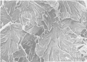


The basic reason for the weakening of the grain boundary---the effect of the material itself or the environmental medium or high temperature
*The intergranular fracture caused by the grain boundary precipitation phase---induced by the inclusion of the grain boundary and the precipitation of the second phase, the precipitation phase on the grain boundary is usually discontinuous, spherical, rod-shaped or dendritic, grain boundary The more precipitation phase, the lower the fracture stress
* The impurity element is segregated at the grain boundary to cause brittle fracture along the crystal—such as Ge, Sn, N, P, As, Sb, Bi, S, Se, Te, and the like. The second type of temper brittleness of low alloy steel (alloy steel is slowly cooled after tempering or grain boundary embrittlement and intergranular fracture at 375-560oC isothermal).
*The intergranular fracture caused by environmental media erosion----hydrogen embrittlement and stress corrosion of high strength steel
* Intergranular fracture at high temperatures.
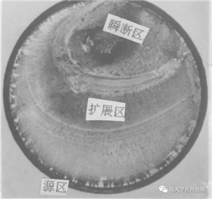
Fracture failure----brittle fracture failure---fatigue fracture <br>The fracture caused by mechanical alternating parts under cyclic alternating stress is called fatigue fracture. In the failure of mechanical components, fatigue fracture accounts for the highest proportion, up to 70%.
Types of fatigue fracture----high cycle fatigue, low cycle fatigue, thermal fatigue, contact fatigue, corrosion fatigue, micro-vibration fatigue, creep fatigue, etc. 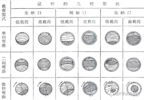
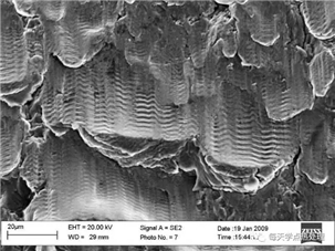
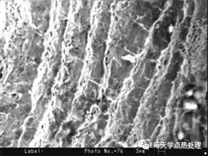

The structure of the part has stress concentration areas such as sharp corners, key grooves and rounded corners;
Material defects such as inclusions, looseness, pores, and microcracks;
Surface defects such as pits, folds, and machining marks;
Heat treatment defects such as surface decarburization, overheating 
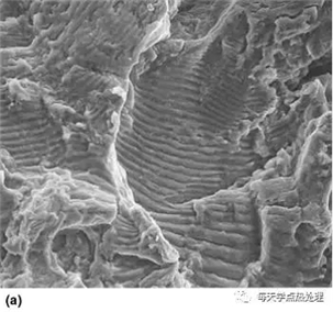
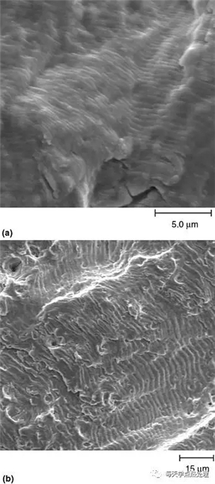

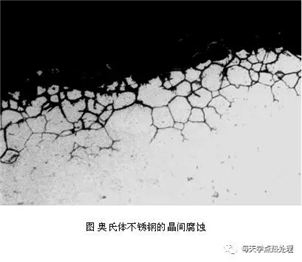


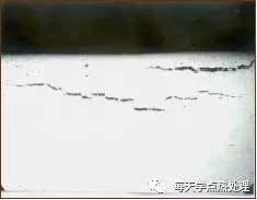

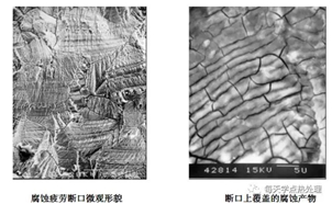

Common wear and tear failures are mainly adhesive wear, abrasive wear, contact fatigue wear, fretting wear, etc. 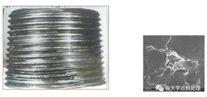
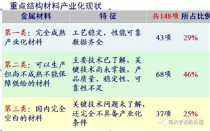
Stable supply of materials only accounted for 29%. 
For the U-shaped specimen, when the impact test is performed, the impact work is mostly consumed by the formation of cracks, and for the V-notched specimen, the impact work is mostly consumed by the crack propagation. Therefore, it is not possible to change the AKV impact test in the original standard to the AKU impact test, which is incomparable and should not be used to lower the standard.
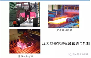
Steel ingot production process 
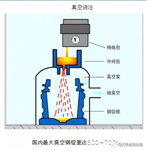
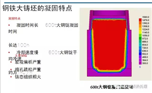

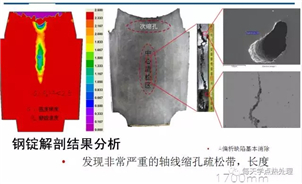
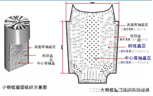
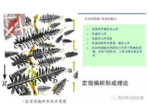
Macrosegregation: long solidification time, severe central defects and type A segregation. 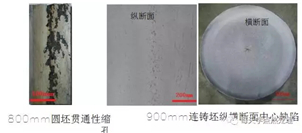

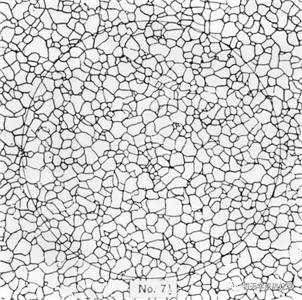


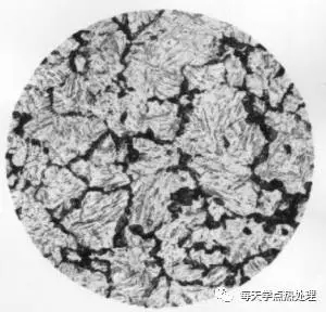
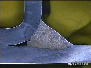
Burning tissue

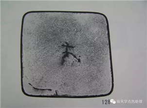
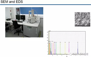
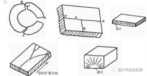
Fracture analysis: It plays an important role in failure analysis. The fracture of the metal material is related to external conditions such as stress, environmental medium, etc., and is related to the chemical composition of the metal material itself, heat treatment, and the like. The appearance of various microscopic fracture morphology basically corresponds to certain internal or external conditions. Therefore, after the fracture of the metal component fails, the shape of the fracture can be analyzed, and the conditions at which it breaks are traced back to determine The fracture mechanism and the cause of the fracture.
Electron spectroscopy: Determine the composition of the microdomains on the fracture.
Chemical analysis 

Tensile test Tensile
High and low temperature tensile test High-low Temperature Tensile
Compression test Compression
Shear test Shear
Torsion test Torsion
Bending test Bending
Flare Test
Cupping Test
Impact test (at different temperatures) Impact (Under Different Temperatures)
Rockwell Hardness Rockwell Hardness
Brinell Hardness Test
Vickers hardness test Vickers Hardness
Leeb Hardness Test
Flattening Test
Mechanical Properties of Fasteners Mechanical Properties of Fasteners
Welded Plate (Tube) Mechanical Properties Welding Plate (Tube) Mechanical Properties
Mechanical performance test


Our company is solemnly committed to the majority of customers: reasonable price, short production cycle, considerate service. We look forward to cooperating with you.