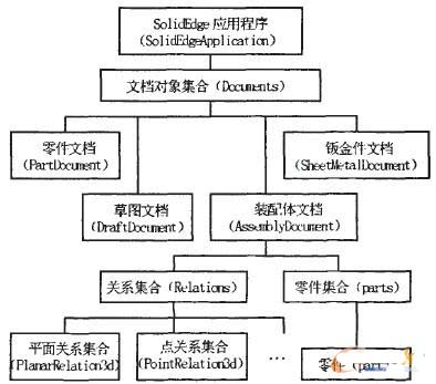
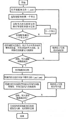
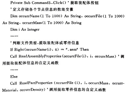
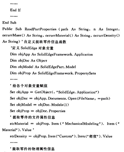
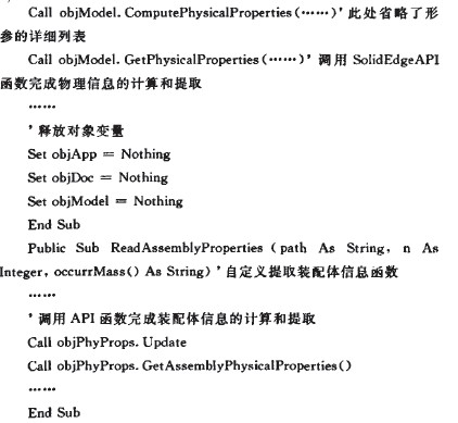
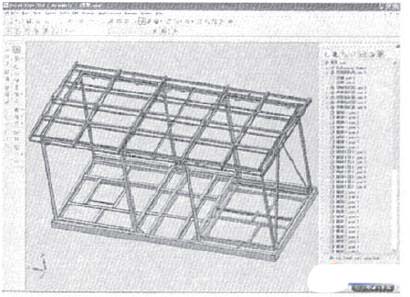
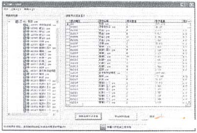
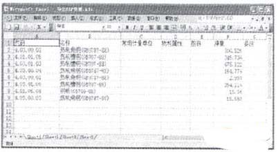
0 Preface With the development of information technology, informatization has become the core of manufacturing enterprises to improve product competitiveness. Bill of Materials (BOM Of Materials) has gradually become one of the core data of the product, and is an important basic data for related applications such as product data management (PDM) and enterprise resource planning (ERP). BOM is an important part of PDM and ERP and the intersection of two major information platforms. It is of great significance to eliminate the "information islands" existing between them. In past product designs, the bill of materials was manually counted by the designer. When designing complex products, the statistical workload of the bill of materials is considerable and prone to errors. Driven by market competition, the design and update speed of products will be accelerated, the design of products will be revised and improved repeatedly, and the BOM of their products will change accordingly. How to maximize the use of BOM information in the design phase is the key to accelerating the transformation of products from design to manufacturing. This research mainly analyzes the product assembly drawing generated by the design stage. With SolidEdge as the development platform, the Visual Basic development tool is used to automatically extract the BOM information from the product assembly drawing, and the extracted information is used as the basic data to generate the intermediate data. Table, used in PDM and ERP system integration. 1 SolidEdge hierarchy and secondary development principles 1.1 SolidEdge object hierarchy Objects are generally interconnected by a form called an object model or an object hierarchy. SolidEdge's object hierarchy is an important foundation for its secondary development. Its object hierarchy can be described as a top-down tree structure, as shown in Figure 1. According to the hierarchical structure of SolidEdge, SolidEdge's secondary development technology can be used to extract the information of assembly BOM information and related components that we need. Figure 1 SolidEdge object hierarchy diagram 1.2 SolidEdge's secondary development principle The Application Interface (SolidEdge API) is the interface for SolidEdge's Object Connectivity and Embedding (OLE) application development. Users can use the SolidEdge API and use the development platform that supports OLE programming to redevelop SolidEdge. Among the many development tools that support OLE automation technology, Visual Basic has the advantages of easy learning, powerful, object-oriented programming, etc., and it is not difficult to find out from the SolidEdge Help file Visual Basic Examples, SolidEdge provides a large number of type libraries with VB interface. The library provides a large number of OLE objects and attributes, methods, and events owned by the object. The programmer can operate these OLE objects and their methods and properties to achieve secondary development of different functions. Secondary development of SolidEdge with Visual Basic development tools requires reference to the type library for SolidEdge in the Visual Basic environment. The application developed by VB and SolidEdge work in a client/server manner, and the user can drive SolidEdge to complete the work by simply operating on the client application. Write code in the VB environment to establish VB and SolidEdge objects and perform various operations on them. 2 Implementation method of automatic extraction of assembly BOM information Adding the assembly drawing of the product in the PDM system, on the one hand, generating a tree hierarchy conforming to the requirements of the PDM management system, and on the other hand, adding the product assembly and extracting the BOM information and related component information in the assembly. Write the extracted information to the database. The process of extracting SolidEdge assembly information and related parts information from the PDM system is shown in Figure 2. The implementation steps and methods are as follows. 2.1 Extracting information about each node in the assembly file In the step of extracting the information, the processing of the product assembly node information (such as the name and the path of the part corresponding to the node) and the processing of the different nodes pointing to the same part or sub-assembly information are mainly completed (in order to make the PDM system not Duplicate management of the same part occurs, and finally the extracted information and the related data obtained after processing are written into the database. The implementation method is as follows: writing functions such as ReadOccurrences() and ReadSubOccurrences() in the PDM system traverse each node to complete the extraction, processing and storage of the assembly node information. The data obtained by this method minimizes the number of times the part file is opened in step 2.3, improving the efficiency of data reading and writing. 2.2 Representing BOM information of an assembly in a tree structure in a PDM system In the above steps, the extraction of each node information in the assembly file is completed and the extracted useful data is written into the database. This step is mainly to call the data in the database to complete automatic coding of the part or sub-assembly. The implementation method is as follows: Write AddRecord() and AddNode() functions in the PDM system to realize the BOM information of the assembly in a tree structure. 2.3 Extracting file attributes and physical attributes of components This step is mainly to traverse the components of each node in the PDM system, open the assembly and part documents under its corresponding path, and automatically extract the file attributes and physical attributes of the components we need. The implementation method is as follows: Write ReadAssemblyProperties(), ReadPartProperties() and other functions in the PDM system to complete the extraction of component file attributes and physical attribute information. 2.3.1 Extraction of file attributes Writing code in VB can monitor the 7 major class parent properties of a document object. From the sub-attribute of the parent attribute, you can find the attributes (ie, sub-attributes) required by the system, such as DocumentName, Material, DocumentNumber, Density, Accuracy, Folder, etc. The names and values ​​of the various sub-attributes accessed in the VB code are: objPropertsets.item (parent attribute) (sub-property).Name and objPropertsets.item (parent attribute) (sub-attribute).Value. Among them, the parent attribute and the child attribute have two expressions: "property name" or Index (sub-property number, an integer). The number of sub-attributes under the parent attribute is of the form: objPropertsets.item (parent attribute).Count. Figure 2 Automatic extraction and storage flow chart of assembly BOM 2.3.2 Extraction of physical attributes The SolidEdge document objects SheetMetalDocument and PartDocument have collection properties Models. For each member model, use the SolidEdge API function GetPhysicalProperties() to get its physical properties. For those physical properties (such as weight) that need to be calculated, you can automatically calculate it by calling ComputePhysicalProperties(). Extracted. The physical properties of the assembly need to be evaluated first and then extracted directly using GetAssemblyPhysicalProperties(). 2.3.3 User Requirements for Creating SolidEdge Documents The premise of extracting the correct file attributes and physical attribute information of the components is that the user has saved relevant information when creating the document, such as the material, density, precision and other information of the parts we need in the actual system. There are two ways for users to create a SolidEdge document that meets the requirements. (1) The user fills in the relevant information step by step in different options when creating the document, and saves it. Fill in the material information and save it in the “Material†option in the menu “Tool†→ “Material Talbe...†of SolidEdge. In the "Tool" → "Variables" → "Variables..." dialog box, find the Name as. Parameters for PhysicalProperties_Density (Density) and PhysicalProperties_Accuracy. Fill in the values ​​that are actually related to production. (2) The user modifies relevant information in the PDM system. Through VB's secondary development technology for SolidEdge, we can not only extract the attributes of the component files, but also modify the file attribute information through the PDM system program. In the PDM system, the function EdiuPartProperties() is written to write the information filled in by the user into the SolidEdge design document. 2.4 Programming Instructions In the secondary development, how to correctly use the API objects and functions provided by SolidEdge is the focus and difficulty of secondary development. After familiar with the calling methods of API objects and functions, write function modules that can implement specific functions according to the requirements of the program. Functions such as ReadOccurrences(), ReadAssemblyProperties(), ReadPartProperties(), EditPartProperties() are all functions that implement specific functions. Define the function. The following is the key code for extracting assembly BOM information: 3 Applied research and examples In this paper, a composite box substation skeleton is taken as an example (as shown in Figure 3), and the relevant information of the assembly has been filled in according to the actual production. Open the product assembly drawing in the SolidEdge environment. You can see the design BOM information of the assembly from the “Assembly PathFinder†option on the right side of the assembly: the total number of parts is 174, the number of different parts is 36; the total number of sub-assemblies is 9. The number of different seed assemblies is 3. Figure 3 Box substation skeleton assembly drawing The assembly is added to the PDM system, and the skeleton assembly BOM information is automatically extracted and added. The assembly BOM information is extracted and written into the database. In the PDM system, a detailed list of assembly BOM information can be viewed, including part name, number, quantity, material, storage path, and the like. The detailed information of each component is shown in Figure 4. The left side of the form is the assembly tree structure diagram. The number of different parts of the skeleton assembly is 36, and the number of different seed assemblies is 4. It can be seen that the assembly BOM information extracted by the system is completely consistent with the information recorded in the skeleton assembly drawing. Figure 4 Assembly BOM information list In addition, the extracted density and material information are checked and the comparison is accurate. Finally, the PDM system uses the extracted assembly BOM information to generate an intermediate data table (Excel table) for the information required by the ERP system. The result is shown in FIG. 5. Figure 5 Intermediate data table The PDM physical data table directly generated by the PDM system is imported into the ERP system through the PDM data import interface provided by the ERP system (the ERP system in this example is Kingdee software), thereby completing PDM and ERP integration. 4 Conclusion This time, SolidEdge is used as a development platform to analyze the internal information expression of the assembly and the internal information expression of the components contained in the assembly. The SolidEdge secondary development interface and database technology are used to extract the SolidEdge assembly BOM information. The PDM system uses the extracted useful information as the basic data to generate the intermediate data table required by the ERP system, and is applied to PDM and ERP system integration. This research breaks the way that the material list in the past product design is manually counted by the designer, which reduces the workload of the designer and has important practical significance. 53Cm Pvc Wallpaper,Modern Chinese Embossed Pattern Wallpaper,Daixin Chinese Style Wallpaper,Modern Striped Wallpaper,Geometric figure PVC wallpaper JIANGSU ARTSTYLE DECORATION MATERIALS CO..LTD , https://www.artstyledecor.com