Pull Down Faucets,Pull Down Faucets Price,pull down kitchen faucet Yuyao Zelin Sanitary Ware Co., Ltd , https://www.zelinshower.com 1 Introduction
At present, green cutting mainly refers to dry cutting and quasi-dry cutting. The range of applications for dry cutting is currently limited, and there are many deficiencies in complete wet processing. If the advantages of the two are combined with each other, the processing requirements can be met, the cost of dry cutting can be minimized, and the same effect as the complete dry machining can be obtained. This processing technique between wet cutting and dry cutting is called Near Dry Machining (NDM) processing or Minimal Quantities of Lubricant (MQL). At present, the complete dry cutting process is more used in the high-speed machining of cast iron materials. In recent years, several European companies have achieved great success in the high-speed machining of gray cast iron parts by dry cutting. However, from the current literature, there is no precedent for complete dry cutting for high-speed milling of titanium alloys. Quasi-dry cutting is mainly used in the processing of cast iron materials, steel and aluminum alloys, and there are few studies on quasi-dry cutting of difficult-to-machine materials.
Some Japanese companies have done a lot of work in the development of nitrogen cutting technology. They have developed a nitrogen gas system that separates nitrogen directly from the air and matched it with the machine tool. The application results show that the biggest advantage is that nitrogen is used as the cutting medium instead of the cutting fluid. Including: (1) overcoming the environmental pollution caused by cutting fluid; (2) tool wear is much lower than dry cutting; (3) high machining accuracy, stable surface roughness; (4) reducing friction and reducing cutting load; ) Safe processing of magnesium alloys (magnesium powder may cause fire, explosion and other safety problems when exposed to water); (6) the use cost is lower than the cutting fluid.
The experimental research on high-speed milling force of titanium alloy will be carried out under dry milling, nitrogen oil mist and air oil mist medium. This paper explores the variation law of milling force under the above conditions. 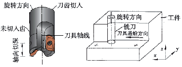
Figure 1 End mill structure diagram and milling diagram 2 test plan
The tool is made of Walter carbide insert end mill, grade ZDGT150416R-K85 WMG40, uncoated, diameter 25mm, corner radius r=1.6mm, two teeth, see Figure 1. The single factor milling force test of high speed milling of ferroalloy TC4 was carried out under dry milling, air oil mist and nitrogen oil mist medium respectively. 3 test results analysis
Test parameters: v c = 190 m / min, a p = 5 mm, f z = 0.1 mm / z, respectively, measuring the milling force at a e = 0.5, 1, 2, 3, 4, 5 mm, the test results are shown in Figure 2. 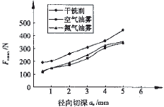
(a) Maximum milling force in the x direction 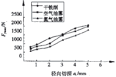
(b) Maximum milling force in the y direction 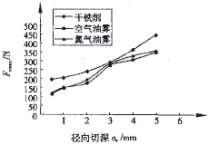
(c) Maximum milling force in the z direction 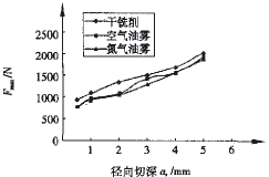
(d) Maximum milling force Fig. 2 Curve of milling force with a e under different media
It can be seen from Fig. 2 that F xmax , F ymax , F zmax , and F max of the three media increase with increasing length , and the increase trend is basically linear, because the radial cut The deepening increases, the milling angle between the tool and the workpiece increases, the milling area of ​​the tool increases, and the friction between the tool and the workpiece increases, so F ymax : increases; the blade milling is used in the test. The helix angle of the tool is 0°, so as the radial depth of cut a e increases, the maximum milling force variation in the x and z directions is not very obvious, which is consistent with the theoretical analysis. Linear and exponential fitting were performed on the curves, respectively, and the correlation coefficient R 2 was above 0.91.
Figure 2(a) shows that the F xmax increases with a e in the three milling media, but the amplitude is less obvious. The F xmax of dry milling is slightly larger than the air oil mist and nitrogen oil mist. From FIG. 2 (b), (c) , (d) it can be seen F ymax, F zmax F max, and with a e of increase is large, similar curves under different medium; mist of air and oil mist nitrogen The F ymax , F zmax and F max are smaller than the dry milling , wherein the dry milling milling force is 22.2%, 15.07%, 25.75%, 5.98%, 8.3% and 5.45% larger than the air oil mist, respectively. 18.3%, 16.6%, 27.5%, 15.96%, 8.38%, and 7.92%. In addition, the milling force under air oil mist and nitrogen oil mist is substantially the same.
Test parameters: v c = 190 m / min, a e = 1 mm, f z = 0.1 mm / z, respectively, measuring the milling force at a p = 1, 2, 3, 4, 5 mm, the test results are shown in Figure 3. 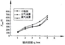
(a) Maximum milling force in the x direction 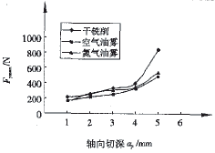
(b) Maximum milling force in the y direction 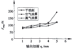
(c) Maximum milling force in the z direction 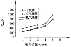
(d) Maximum milling force Fig. 3 Curve of milling force with a p under different media
It can be seen from Fig. 3 that F xmax , F ymax , F zmax , and F max of the three media increase with the increase of a p , and the increase trend is basically the same. Linear and exponential fitting were performed on the curves, and the correlation coefficient of the exponential fitting was found to be high (R 2 ≥ 0.93). The milling force and resultant force during dry milling are greater than that of air oil mist and nitrogen oil mist, and the results are similar to those of the previous section.
When a p is greater than 5 mm, the milling force increases, which may be caused by the increase of a p , the milling force increases, the rigidity of the tool system decreases during milling, and the milling cutter is prone to vibration.
Test parameters: v c = 190 m / min, a e = 1 mm, a p = 5 mm, respectively, measuring the milling force at f z = 0.5, 0.1, 0.15, 02, 0.25 mm / z, the test results are shown in Figure 4. 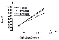
(a) Maximum milling force in the x direction 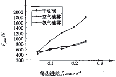
(b) Maximum milling force in the y direction 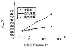
(c) Maximum milling force in the z direction 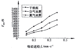
(d) Maximum milling force Fig. 4 Curve of milling force with f z under different media
It can be seen from Fig. 4 that F xmax , F ymax , F zmax , and F max in the three media increase with the increase of f z , and the curves are linearly and exponentially fitted respectively, and two kinds of fits are found. The correlation coefficient R 2 is approximately the same and R 2 is higher, which is different from the theory at low speed milling. At low speeds, as the f z increases, the milling forces increase overall, but the increase in milling force does not increase proportionally with the increase in feed. Since the feed amount is increased and the cutting thickness is increased, the cutting area is increased, and the force is increased accordingly. However, as the cutting thickness is increased, the deformation coefficient is decreased and the friction coefficient is also lowered, so the force is increased and the feed amount is increased. The increase is not proportional. At high speeds, since the temperature in the milling zone is much higher than the low speed, the chip on the rake face of the milling cutter and the machined surface in contact with the flank of the milling cutter are very plastic. Therefore, the thickness of the cutting increases and the deformation coefficient is greatly reduced. Low, the coefficient of friction is also reduced very small, so the increase in force is roughly proportional to the increase in feed.
It can be seen from Fig. 4(d) that as the feed per tooth (f z ≥ 0.1 mm/z) increases, the milling force under the nitrogen oil mist is significantly lower than that of the air oil mist. According to foreign research data, under high feed, the milling heat increases, and the TiN layer is more likely to be generated between the tool and the chip and the workpiece under nitrogen. Because TiN has anti-friction effect, it is generated by friction during milling. Milling forces are reduced.
The test parameters were: aa e =1 mm, a p =1 mm, f z = 0.1 mm/z, and the milling forces at v c = 190, 250, 275 and 300 m/min were measured, respectively. The test results are shown in Fig. 5. 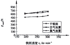
(a) Maximum milling force in the x direction 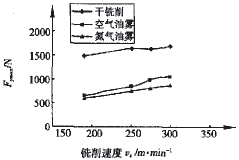
(b) Maximum milling force in the y direction 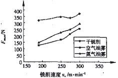
(c) Maximum milling force in the z direction 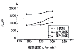
(d) Maximum milling force Fig. 5 Curve of milling force with v c under different media
Figure 5 shows that F xmax , F ymax , F zmax , and F max in the three media increase with increasing v c , and the fluctuation is not large, which is different from the traditional cutting theory. Conventional cutting theory believes that the cutting force generally decreases as the cutting speed increases. This is mainly because the increase in v c will increase the cutting temperature and decrease the friction coefficient μ, thereby reducing the deformation coefficient x . For the law of cutting force changing with cutting speed during high-speed cutting, some foreign scholars have also done relevant experimental research. Amdt believes that due to the presence of high-frequency impact forces during ultra-high-speed cutting, the change of cutting force is the result of both the traditional cutting force and the high-frequency impact force. Kusnetsov and Sutter test the aluminum alloy AA7075 and alloy steel AISI1045 at high speed. As a result, they concluded that high-frequency impact forces are also present in high-speed milling, which is consistent with Amdt's theory.
When milling titanium alloy at high speed, the increase in speed will also reduce x , but milling is interrupted cutting. The force generated by the impact occupies a considerable proportion of the entire milling force. The higher the speed, the greater the impact. The increase in milling force due to high-speed impact is much greater than the reduction in milling force due to the reduction of the deformation coefficient x . Therefore, when milling titanium alloy at high speed, the milling force increases as v c increases.
As can be seen from Figures 5(a) and (d), the variation of F xmax and F max is similar to that of the previous section. When the milling speed exceeds 200 m/min, the F max under air oil mist is greater than the nitrogen oil mist. Especially when the milling speed reaches 300 mm/min, the F max under air oil mist is 32% larger than the nitrogen oil mist. The reason for this result is that, in addition to the TiN friction reduction effect, the TiN in the chips under the nitrogen oil mist at high speed is increased, so that the chips are easily brittle and the friction and impact of the chips on the cutter are reduced. 4 Summary