Solar Street Light,LED Solar Light,Solar Street Light,Solar Garden Light Jiangmen Dilin Lighting High-Tech Co., Ltd. , https://www.jmdilinlighting.com


Button housing blanking-drawing-punching composite die design
1. Part structure
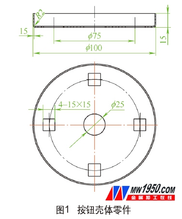
The button housing of Figure 1 is a part of a product, using 1.5mm thick 304 stainless steel, the production volume is large. Because it is an appearance part, the surface of the part is required to be high, and defects such as obvious thinning and deep drawing are not allowed.
2. Processing technology analysis
This is a common typical bottom with hole shallow drawing parts, the structure of the parts is not very complicated, the drawing height is not large, the size requirements are not high, the shape of the workpiece meets the requirements of the drawing process, and the whole part has a good drawing process, but The bottom square hole is closer to the wall of the shallow cylinder, and the nearest part is only about 3 mm, which is easy to influence each other during the punching or deep drawing process. It is necessary to take corresponding measures in the mold design to avoid it.
According to the structure of the part, it is known that the processing of the part can be completed by blanking, drawing, punching, etc. In order to determine the part process plan, the process calculation of the part is first required to formulate a reasonable process plan.
Considering the use, the parts are not required to be deep and the depth is deep, so no trimming margin is left.
It can be seen from Fig. 1 that H=15-1.5/2=14.25 (mm); d2=100-1.5=98.5 (mm); r=2+1.5/2=2.75 (mm) (where the part diameter d2 is the center layer diameter). According to the principle of the surface area of ​​the blank and the workpiece before and after drawing, the formula is calculated according to the diameter D of the unfolding material, and the corresponding value is obtained.
After rounding, take D=122mm, then the drawing coefficient of the part
Relative thickness of the blank
When judging the drawing, whether the pressing edge is 0.045 (1-m)=0.0086, because >0.045 (1-m), the crimping ring can be omitted.
Check the relevant data, the first limit drawing coefficient of stainless steel m pole = 0.52 ~ 0.56, because m> m pole, it can be deepened at one time.
According to the above process calculation, taking into account the requirements of the use of parts and the need of mass production, it is decided to use a set of blanking, drawing and punching composite molds to complete the parts processing at one time. The processing technology of the parts is: cutting strips → blanking, drawing, punching.
3. Mold structure
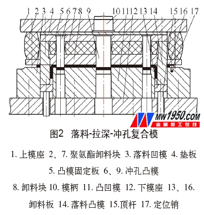
Designed blanking, drawing, and punching composite molds, as shown in Figure 2. When the mold is working, the press slider is raised, and the press ejector cylinder pushes the unloading plate 13 to the plane of the convex and concave die 11 through the ejector pin 15. At this time, the cut strip is placed on the convex and concave die 11 And the upper end surface of the stripper plate 13 is positioned by the positioning pin 17, and the stripping plate 16, the blanking punch 14 and the stripping plate 13 first press the strip with the downward movement of the press slider, As the press slider continues to descend, the blanking die 3 and the blanking punch 14 blank the blank. At the same time, the blanking punch 14 cooperates with the convex and concave die 11 to deepen the blanked sheet. As the slider of the press continues downward, the unloading block 8 is in contact with the sheet while the drawing is completed. The surface of the hole to be punched is pressed, and the slider of the press continues downward. The punching punch 6 and the punching punch 9 work together to complete the punching of the five holes at the bottom of the button housing, and the parts are processed.
With the upward movement of the press slider, under the action of the polyurethane discharge blocks 2, 7, the discharge plate 16 and the discharge block 8 are respectively reset, and at the same time, the press ejector cylinder passes the ejector plate 15 through the discharge plate 13 The parts which are finished blanking, deep drawing and punching are pushed out of the convex and concave die 11. After the parts are taken out, the strips are fed in, and the next pressing process can be performed to complete a working cycle.
4. Design points
The key to mold design is to ensure that the three composite processes of blanking, drawing and punching can be completed in order. Otherwise, when punching four square holes, it will be too close to the wall of the deep drawing. The flow of the wall material causes the hole to be deformed, and the material locally appears to be sharply thinned, causing defects such as depressions. To this end, the mold structure design has the following characteristics.
(1) The blanking punch 14 has a dual function, which is not only a convex die with a blank shape but also a concave die for drawing a part; the convex and concave die 11 also has a dual function, which is a punch for deep drawing of parts, and is also punched five. a die of holes.
(2) The height of the working parts such as the punching punches 6, 9 and the blanking punch 14 should be controlled. The working faces of the punching punches 6, 9 must be 15 mm below the lower end of the blanking die 14 to ensure that the parts can be deepened. After completion, the material of the wall of the part is plastically deformed, and punching is performed after the metal flow is completed.
(3) In the free state, the lower end surface of the discharge block 8 should be 13 mm higher than the lower end surface of the blanking die 14, that is, when the blank is deepened, the discharge block 8 does not press the blank, thereby ensuring the deep drawing process. The metal material at the bottom corner of the deep drawing piece flows more freely and smoothly.
5. Use effect and conclusion
Since the blanking, deep drawing and punching composite molds are designed to better combine the various processes, and effective measures have been taken for the problems caused by the composite, the test design and manufacture are qualified once, and at the same time, Increased production efficiency. In the past year, about 30,000 parts have been produced, the quality of the products is stable, and the molds work well. The mold structure is also applicable to other similar shallow drawing parts which are not required for the drawing height.
About the author: Pan Xin, Zhejiang Wilkinson Elevator Co., Ltd.; Zhong Xiangshan, Changlin Machinery Company, Changchun Group, Xinyu City, Jiangxi Province, Technical Department.