Typesetting and output of 2D process cards based on DELMIA
1. Background and needs analysis
The process personnel use DELMIA's DPM module and process design based on the 3D model to achieve feature-based process development. The process can be presented in a structured data manner and can display 3D models at different stages. However, the process personnel encountered great difficulties in applying the current mode of operation, and could not accurately, dynamically and automatically correspond to the output of the process results, resulting in the three-dimensional digital process still staying at the data level, and not applied to the actual production and processing to guide the production. There is no benefit to the three-dimensional digital process for the enterprise, so the conversion and conversion of the three-dimensional digital process into a two-dimensional process card has become a bottleneck in digital manufacturing. Through the analysis of the current situation of the business, the demand shown in Figure 1 is obtained.
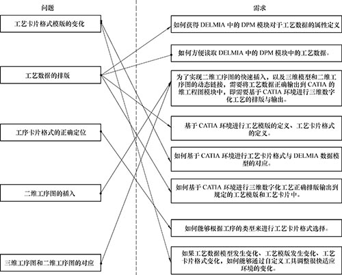
Figure 1 Business needs
2. Solution analysis
The workflow in the DELMIA 3D process design environment is different from the 2D process design process. The process design work is completely carried out in the DLM module of DELMIA. The process data can be output in the form of XML. If you need to modify the process data, you need to go back. Go to the DPM module of DELMIA. In order to keep consistent with the standardization of the enterprise, through the secondary development, the XML data is converted into an Excel format report, wherein the Excel format template defines the process card format used in advance and represents the corresponding relationship, and corresponds to the three-dimensional digital process attribute. If there is a 2D process diagram, the 3D model is projected into a 2D process diagram in a CATIA environment and inserted into an Excel report. Through the combing of the workflow, it is determined that the developed two-dimensional process card layout and output system must have eight functions below.
(1) Reading the 3D digital process data model in DELMIA: The process data model defined in DEPMIA's DPM model can be correctly obtained, including product information, part information, process, process information, tooling and tools, and object inclusion. The name of the property.
(2) Define the process specification template: set a process card of a set of process rules, each process card should include the type of card, whether there is a continuation page and the order of appearance.
(3) Define the process card format: Define the attributes of each or each column of cells according to the process card format drawn in the CATIA 2D drawing module, including the corresponding 3D digitized process data model attributes, fonts, and output control methods. And color, etc.
(4) Define the output rules: adjust the output order of the process cards, the width of each line, the processing of the continuation page, and whether the user is allowed to select the card format.
(5) Read the 3D process data file in DELMIA: obtain the process information in the DELMIA output process data file, and correspond the process information according to different cards and objects.
(6) Setting layout requirements: According to the defined output rules, before the user performs the layout of the process data, the layout is set again to meet certain special requirements.
(7) Process data layout: The process card graphics are loaded according to the defined process template, process card format and defined output rules. The layout of the process data is performed, and the process data is correctly output to the CATIA 2D drawing according to one view per page.
(8) Process data output: According to the defined output requirements, it is printed out through the plotter.
3. System architecture
The system architecture is shown in Figure 2. It is divided into data layer, support layer and application layer. The data layer mainly includes the DELMIA process data model, the generated process files, the process cards supporting the typesetting, and the card format configuration library; the support layer is mainly for supporting the association between the process data model and the process card, and the layout of the process data; The layers range from the process data generated by the DELMIA to the layout requirements, to the process data layout, and finally to the process data output.
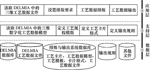
Figure 2 System architecture
4. System function structure
The system function is shown in Figure 3. It includes five parts: process data model acquisition, process template definition, process card format definition, process data reading and process data layout. Among them, process data model acquisition, process card format definition, and process data layout are the key technical parts of the whole system.
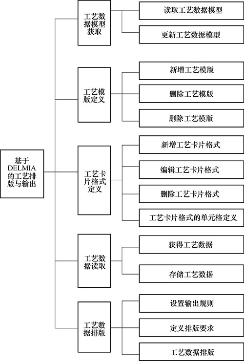
Figure 3 system function structure
(1) DELMIA-based process data model reading method. From the currently loaded 3D model attribute information, based on the process information model, the internal process data model is extracted through the obtained DELMIA-based development interface, thereby generating structured data and establishing an object class containing process information. . Object classes mainly include CPPBWorkspace, CPPBObj, CPPBPart, CPPBProd, CKBClass, and CKBAttr. Corresponding to CPPBWorkspace is a complete process specification. Corresponding to CPPBObj is the general object in the process information (such as process, work step and tooling, etc.). Corresponding to CKBClass is the object class in the process information (such as machinery). Processing class, process class, etc.), corresponding to CPPBPart and CPPBProd are part objects and product objects, and CKBAttr corresponds to a certain attribute of the object class. All CPPBObj objects and products and part objects are determined by the CKBClass object class (for example, the members of the CPPBProd object are determined by the object properties defined in the product object class, and the members of the CPPBObj process object are defined by the object properties defined in the operation object class. Determined). It is known from the definition of the process information model that a process specification includes not only one process basic information object and multiple process objects, but also product or part objects; the process basic information object and the process object may also contain sub-objects (such as materials). The object and the blank object are included in the process basic information object, and the tooling object, the device object, and the step object are included in the process object). The process information object relationship is shown in Figure 4.
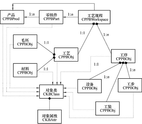
Figure 4 Process Information Object Relationship
(2) CATIA-based process card format definition. For a standard manufacturing enterprise, various types of process card formats are executed according to certain standards (such as national standard or enterprise standard), and many different types of process cards constitute a complete process specification document. In other words, for each type of process documentation, there are certain format requirements. Therefore, the standard templates to be used must be defined in advance. The format of these defined templates must also conform to the corresponding standards.
Customized process card template: The process card is drawn in Excel according to certain standards or specifications, and then the relationship with the process information model is established in the form of the card to form a process card template. According to the direct relationship between the process card template and the process information model, the process card templates are classified, and the classification results are shown in the attached table.
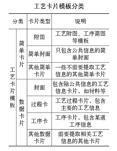
Definition of process specification template: A process specification template is a collection of card templates consisting of one or more process card templates in a certain order according to enterprise standards. The defined process specification template must include at least one process card template. The process card templates can be customized according to the different needs of the use, and the process specification template can be customized.
Mapping of process card templates and process data models: From an information point of view, process cards contain product information (product model and product name, etc.), part information (part model number, part name, etc.), basic process information (eg process method) , implementation of standards and materials, process information (process number, process name and equipment model, etc.), work step information (work step number, work step content, etc.), etc., the object class in the process information model and these attribute information is established One-to-one correspondence. From a tabular perspective, craft card templates can be subdivided into tables, cells, rows, and columns. A table is a combination of multiple columns, and at the same time, the column is composed of multiple cells. Taking the filling habit of an enterprise craft card as an example, the contents of the same column of cells are generally the same type of information, and the rows correspond to different types of information (such as processes and steps). A cell can be thought of as a column that contains only one cell. Therefore, in the process of customizing the process card template, only the definition of tables and columns is required to complete the customization work.
In the process of customizing columns, you need to associate the columns in the card with the object properties in the process information model. The column contains not only the information about the process information model object, such as the object name, object attributes, and the parent-child relationship of the object, but also the processing method, font and name of the data. With this information, the process data can be easily exported to the corresponding card.
In addition, in order to make the process data more convenient in subsequent layout, according to the attributes of the process information, the columns are divided into five levels: product level, part level, process level, process level and work step level; And a plurality of cell columns together (such as process information in the process card and step information in the process card) are defined as tables.
(3) CATIA-based process data layout. When designing the process data layout function, it is necessary to ensure the correctness of the current data transmission, but also to consider the changes brought by the system upgrade in the future, and to facilitate the routine maintenance of the system administrator. Therefore, a typesetting file containing two parts of general information and class information is defined in the system to match the process data layout.
General information: The first two lines of the layout file are the overall information, including the total number of pages, page number, maximum number of loop lines, page loop flag, page type name, process card flag and step flag, for example, "begin_of_page/1 , 20, N, jjgyk, the main loop home page.
Class information: The main part of the typesetting file is class information, which consists of five parts: step, process, process, component and product. Each part contains several subclasses. Each subclass has similar structure, including parent class. Name, class name, attribute name (except for the five parent classes, such as step, process, craft, component, and product, the subclass needs to give the parent class name and attribute name to call the subclass), @H, and @S .
5. The output of the typesetting file
(1) Define class information. After the file is typeset, the label in the card corresponds to the attributes of each class defined in the above definition. The definition is in a dialog box, which is defined class by class and added to the typesetting file.
If you need to define a class of new documents, follow the order of "products, components, processes, sub-categories of processes, sub-categories of operations, sub-categories (several), sub-classes of work steps and work steps (several)" Definition, the various attributes correspond to the label. For a class, first double-click its class name. If the class is a class other than the five categories of products, components, processes, processes, and steps, that is, subclasses, select the class in the pop-up dialog box. First-level parent class, if the double-clicked class is not required for the layout file, click Cancel, and then double-click the property name of the class in the Object/Object Table Property Name column (automatically put in the corresponding box) ). Select the "Arrangement of this type of object" item (not selected, the default is the first item). In the "All Tags in Card" column, double-click the tag that belongs to the attribute that belongs to the category. This tag is automatically filled in the edit box. Double-click the attribute corresponding to this tag in the "Attributes of this class" column. Name (one or more), or click the attribute name, click the "correspond" button, click the "end" button, and then click the "join" button, a label line is formed, continue to define this method All label lines under the class.
To modify a label line that has already been added, double-click on the corresponding label line, make the changes in the edit box below, and click the Update button. After completing all the tag row definitions under this class, click the "One class defined" button. And so on, the label lines under other classes are also defined. The "List of class names that have been added" shows the class names that have been defined in the layout file. If there is a lastset or set command line in a class, select it in the "command line information" column (for example, "interlace typesetting" corresponds to newline, "continuous typesetting" corresponds to sameline, "last object" corresponds to lastset, "all objects" Corresponding to the set, the group number defaults to "Y"). Then, in the "Properties/Label Corresponding to This Class" column, click the location where you want to insert the command line, click the "Format Display" button and the "Add" button. After all the class definitions are completed, click the "All Classes Defined" button and click "OK" to complete the definition of the layout file.
If you need to modify a file, double-click the name of each type according to the above method, and modify it. Click “One type of definition completed†button after modification. If you do not need to modify, double-click the class name and click “One type of definitionâ€. Finish button. Finally, click on the "All Classes Defined" and "OK" buttons to complete the modification of the file.
(2) The connection of the typesetting file. The above defines a page of the typesetting file. If the layout file has multiple pages, define each page separately (note the total number of pages and the page number of each page) and name them separately. After each page is defined, click the “Connect Typography Page†menu item. In the pop-up dialog box, click the “Select Page Segment†button, select each page in order according to the prompt, and finally, click “OK†to complete the connection. , generate a complete layout file and name it. The typesetting file consists of two parts: general information and class information.
(3) Process data layout output. To output the process layout file, you need to go through the following steps: 1 Select the data file and read the data (see Figure 5). 2 Modify the layout file and set the layout parameters (see Figure 6). 3 process data layout and result preview (see Figure 7). 4 process data layout results (see Figure 8).
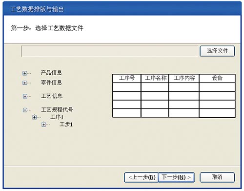
Figure 5
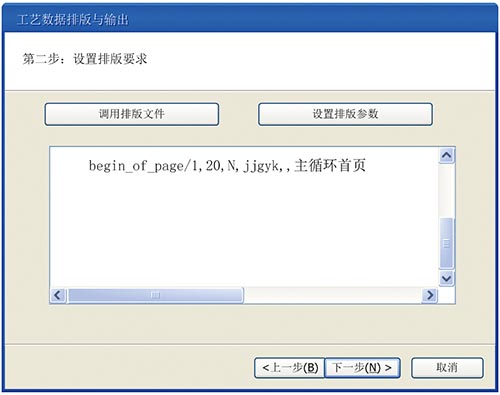
Image 6
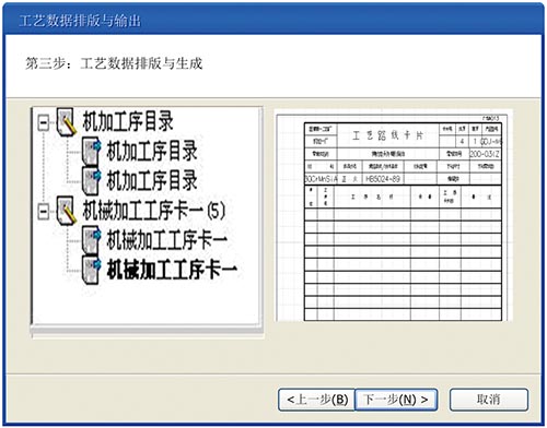
Figure 7
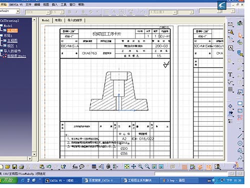
Figure 8
6. Conclusion
Converting the 3D visualization process into a 2D process file for use at the production site is a transitional part of the digital process system construction, due to the fact that the hardware used at the production site (such as inspection equipment and browsing equipment) is not available. The three-dimensional process is directly issued to the requirements of the production site, and the compromise is adopted. In the future, with the continuous improvement of the hardware level, the production environment with full three-dimensional process will be realized.
references:
[1] Hu Ting, Wu Lijun. CATIA secondary development technology foundation [M]. Beijing: Publishing House of Electronics Industry, 2006.
[2] Wang Zheng. Excel 2007 VBA Application Development [M]. Beijing: Publishing House of Electronics Industry, 2009.
[3] Wang Zhanhai, Zhai Qinggang. A Preliminary Study on the Secondary Development Technology of DELMIA[J]. Journal of Xi'an Aeronautical Technology College, 2010, 28(1): 1-3.
(Received date)
Chemical Industry Injection Package
*Skid(chemical dosing skid) and package is fit both customer specification and international standards
* Both manual control & remote control can be as the optional.
* The integration system design, overcomes the defect of only the signal units.
* Customised design to meet of the requirement of different demand.
*All kinds of brand, material and parts can be available with different projects.
Odm Chemical Industry Injection Package,Plastic Chemical Industry Injection Package,Plastic Industry Chemicals Injection Package,Chemical Dosing Skid
Zhejiang Ailipu Technology Co., Ltd. , https://www.alipu.com